Digital Signage: Measuring and managing power consumption for EMCs
by all | 14 September 2016 10:00 am
 [1]
[1]Photos courtesy Sunitron
By John P. Heath
There are many ways to measure the power consumption of an electronic message centre (EMC). One could add up the power supplies and heaters; or calculate consumption for each light-emitting diode (LED) and set the duty cycle at 65 per cent; or calculate an average that is much less than the sign’s maximum power level.
With a typical EMC, 95 per cent of the power is used by direct current (DC) power supplies to provide stable, regulated voltage to the LED modules. The other five per cent is used by the cooling fans and standby idling current.
Duty cycle
The duty cycle of an LED-based EMC relates directly to the sign’s brightness and its degree of power consumption.
Using ambient light sensors, EMCs can be brightened or dimmed based on the client’s needs. That is not to say the electronics within the sign can accommodate ‘medium-bright’ or ‘dim’ LEDs. Rather, they can only turn the LEDs on—i.e. to full brightness—or off. Dimming effects are instead accomplished through the clever trick of changing the duty cycle of the LEDs.
This process, which involves adjusting the amount of time each LED is on or off, is commonly referred to as Class D modulation. A ‘medium-bright’ LED has a 50 per cent duty cycle, as it is only on for 50 per cent of the time. A ‘dim’ LED has a duty cycle of 10 per cent, as it is on for only 10 per cent of the time and off for the other 90 per cent. A dimmer control for LED illumination of a room works on a similar principle, changing the duty cycle to dim the lights.
The relationship between duty cycle and power consumption is a 1:1 ratio. If the duty cycle is increased by 10 per cent, then the power consumption rises by 10 per cent, too.
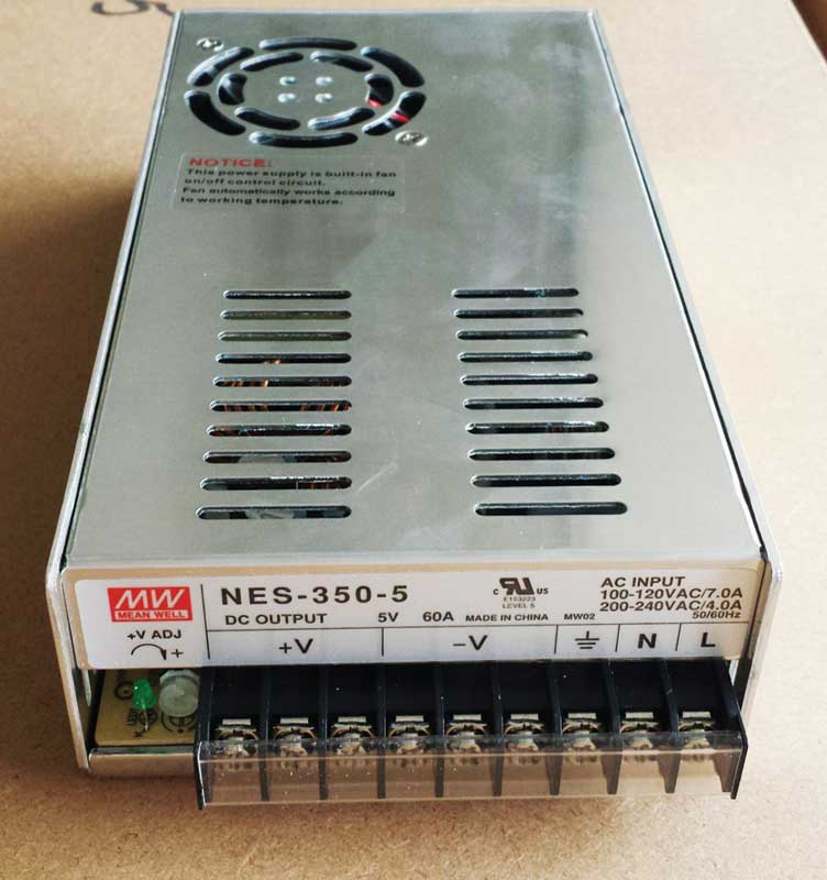
One way to measure the power consumption of an EMC is to add up its power supplies (example pictured) and heaters.
Minimum, average and maximum
An EMC’s minimum and maximum power levels are determined by its number of LEDs and their brightness. An EMC might consume 1,000 W in sunny daytime conditions at a 90 per cent duty cycle, for example, before being dimmed at night to a 10 per cent duty cycle and consuming only 150 W. Given the various duty cycles within a 24-hour period, the average power consumption of the sign may realistically be around 400 W.
A true root mean square (RMS) ‘clamp amp’ power meter can be used to measure consumption of electricity, but an EMC—with all of its various components—is not so simple to summarize. Other issues include: what kinds of messages the sign is displaying (e.g. still images or full-motion video); how many LEDs are lit to display these messages, in which colours; and which duty cycles are used, for how long.
With these factors in mind, one of the better approaches is to determine the absolute highest possible ‘peak’ power consumption of a given sign. This scenario would entail every LED being illuminated at a 90 per cent duty cycle. At the other end of the spectrum, shutting all of the LEDs off will yield the sign’s lowest possible power consumption.
The ratio between these two ends of the spectrum is usually about 10:1, e.g. with maximum power of 1,000 W and minimum power of 100 W.
The maximum/peak power consumption is important to understand so electricians can select the right breaker for the sign, as they can ascertain the servicing requirements. The average power consumption, on the other hand, is important to understand so the client can estimate ongoing electricity costs to run the sign.

The duty cycle of an EMC relates directly to its brightness.
Permits and codes
Power consumption does not have any obvious impact on acquiring permits or following local sign codes, but it is indirectly related, in the sense that sign brightness is often considered a public safety issue. A sign that is too bright at night, in particular, may not be permitted for fear of distracting drivers on the road.
Fortunately, EMC manufacturers have pioneered optimal ‘formulas’ for properly blending colours and light so as not to disturb nearby traffic patterns. At the same time, they are also optimizing visibility and legibility. Amber LEDs, for example, are the easiest to read for colour-blind passersby, while many municipalities are banning red.
Components
Most EMCs are built similarly, but not with the same quality of components. Standard components mean replacements can be sourced as needed from a local store. Odd non-proprietary plugs and cables, on the other hand, cannot easily be bought off the shelf. This is why it is better—both for the manufacturer and for the customer—to use standard plugs, cables and connectors.
Processing and compression
Dedicated read-only memory (ROM) state machines, also known as programmable logic arrays (PLAs), offer high processing speeds in the 200 MHz range, without needing additional heat sinks and fans to ensure their reliability. One might wonder why so much ‘horsepower’ is needed for a simple EMC; the answer lies in the aforementioned Class D modulation of the LEDs.
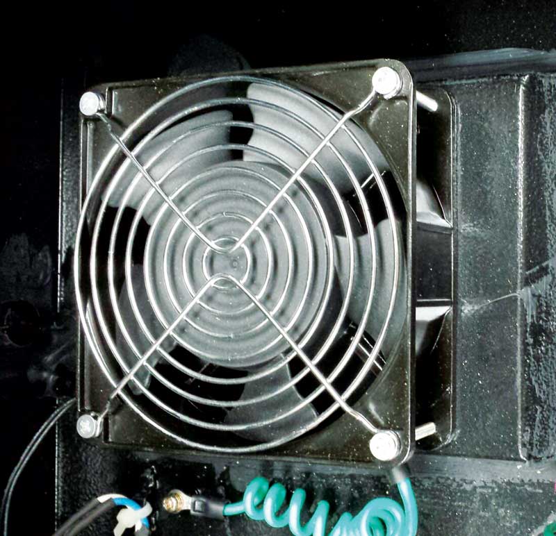
In a typical EMC, five per cent of the power is used by the cooling fans (example pictured) and for standby idling current.
If a sign has a refresh rate of 100 Hz, then it must clock out 128 bits of data for one line of LEDs from left to right, 100 times per second. This modulation rate of data transmission is expressed as 12,800 baud (Bd), representing 12,800 bits per second. Such a rate is easy to achieve, even with old chips, but there is an additional burden when using Class D modulation. To achieve a greyscale of 256 for a red, green and blue (RGB) display, the data rate goes up from 12,800 to 3,276,800 Bd.
That is about 3 MHz, which may not seem like a big deal, but the requirements do not stop there. For the sign’s colours to be dimmed at night, a minimum greyscale of 32 must be added to the 256, which brings the sign up to 100 MHz Many older chips were limited to only 10 MHz, but there are inexpensive 1-GHz 32-bit microprocessors today that are up to the task at hand.
That would be sufficient, of course, if an EMC only featured one line of 128 LEDs. Rather, the average EMC features 64 lines of each of three colours (i.e. RGB) of LEDs, boosting the processing speed requirements from 100 MHz to 20 GHz—a level of microprocessing technology that is not available today. This certainly poses a challenge for designing a full-colour LED EMC that can display full-motion video.
Yet, such signs obviously already exist in the real, despite the technology seeming to be impossible. The answer is to ‘cheat,’ using compressed video files. This process involves several data compression algorithms.
The first algorithm is horizontal. If an RGB pixel exhibits cyan brightness of 128 out of 256 greyscale, for example, then there is a good chance the pixel next to it is equally bright. There is no point in using valuable bandwidth by transmitting two pixels when one will do the job, set with 1-bit parity to indicate the neighbouring pixel is the same colour. Doing so achieves 50 per cent compression.
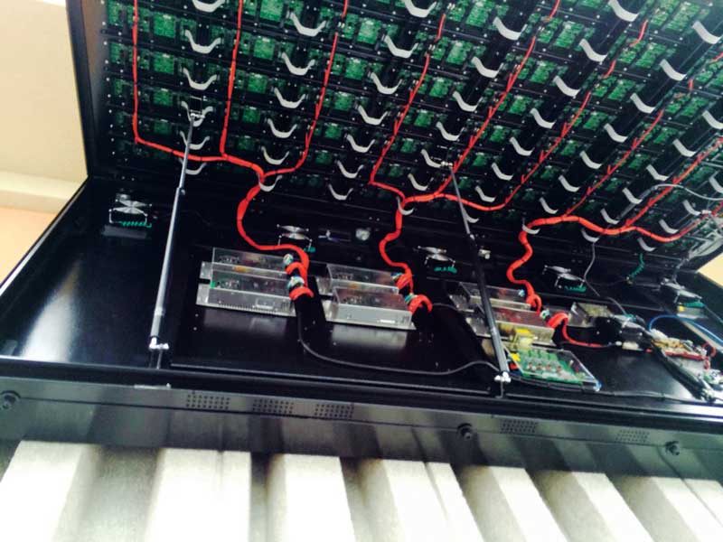
With advances in electronic technology, an LED-based EMC should run reliably for about 10 years before it needs to be opened up for maintenance.
The second algorithm is vertical and works in exactly the same way. By taking advantage of redundancy compression, it becomes possible to display an image with only 25 per cent of the original video information.
The third algorithm relates to time. When a single frame of video is displayed, there is a high probability the next frame is the same. Time compression is more significant than horizontal and vertical algorithms combined, as it can achieve compression somewhere in the neighbourhood of a 10:1 ratio.
With all three algorithms in effect, a 1-GB video file can be compressed to just 25 MB, without destroying any of the original video information. With ‘destructive’ algorithms, the net compression of file size is even more impressive, but the displayed image is of lower quality. In some cases, however, highly destructive algorithms are cleverly designed enough that it is hard for the average passerby to notice a large-scale EMC is missing data.
In these ways, the sign industry has been able to source Video Graphics Array (VGA) or Digital Visual Interface (DVI) output from computers and use compression software to drive content effectively onto EMC screens.
John P. Heath is a senior technologist for Sunitron in Concord, Ont., which manufactures and distributes programmable electronic light-emitting diode (LED) signs and indoor and outdoor display systems. For more information, visit www.sunitron.com[2].
- [Image]: http://www.signmedia.ca/wp-content/uploads/2016/09/power_64x144-20mm-e1472759624764.jpg
- www.sunitron.com: http://www.sunitron.com
Source URL: https://www.signmedia.ca/digital-signage-measuring-and-managing-power-consumption-for-emcs/